Your AIS receiver will require the following items:
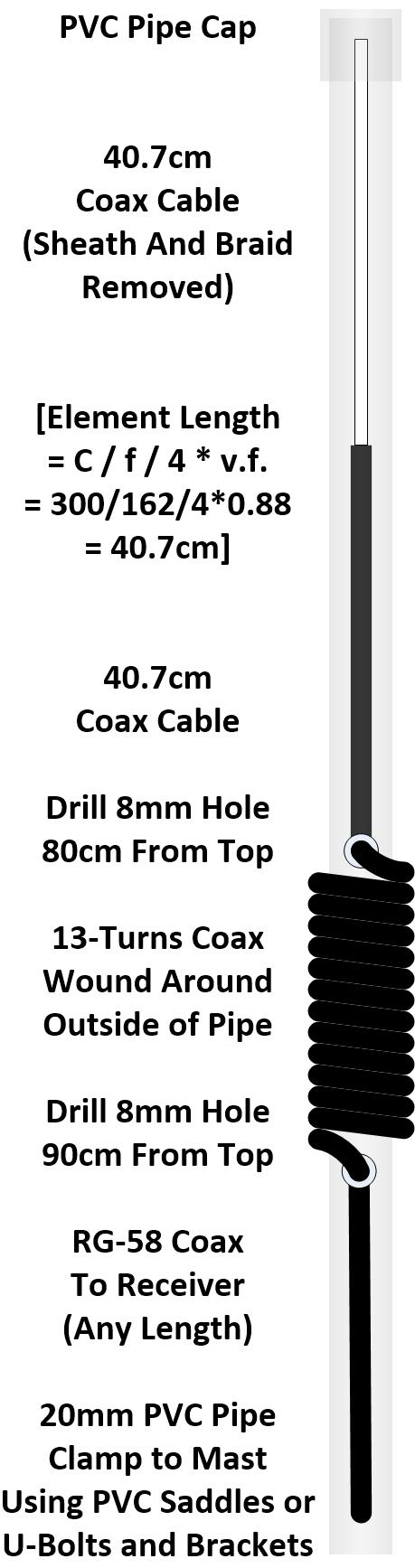
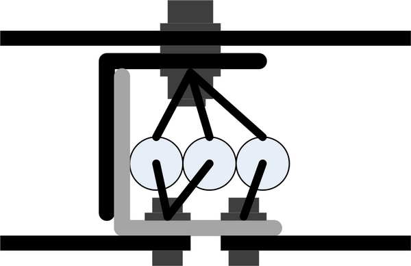
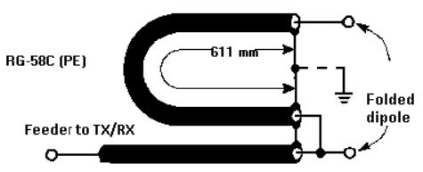
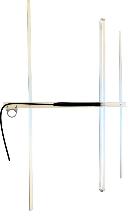
- 162MHz AIS vertical antenna. See above for the simplest design or here for other ideas.
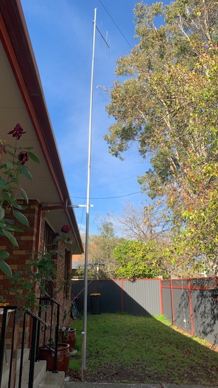
- Antenna mast. High enough to mount the antenna within line of sight of ships.
- Coaxial cable (50 Ohm, e.g. RG-58) from the antenna to the AIS receiver, with an SMA connector
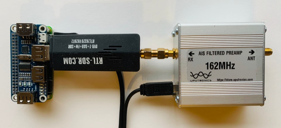
- AIS Filtered RF Preamplifer - 162MHz (Only needed for poor reception areas). See: www.uputronics.com.
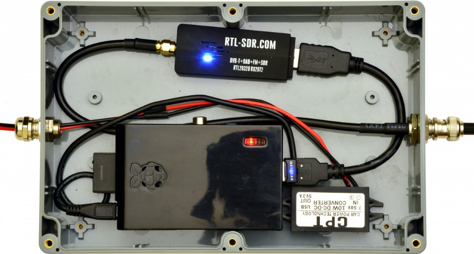
- Weatherproof, non-metallic (for Wi-Fi access), enclosure for mounting the hardware
- Raspberry Pi (RPi) single board computer. Any version: 0,1,2,3,4, model B or B+. See: www.raspberrypi.org.
- USB Hub Hat with micro USB joiner (Only required for RPi0). See: www.waveshare.com.
- USB Wi-Fi dongle to suit your home Wi-Fi router (Not required if your RPi already has Wi-Fi)
- USB RTL-SDR dongle (TCXO 1ppm or better). See: www.rtl-sdr.com.
- USB extension cable, 10cm (Not required for RPi0 with Hub Hat)
- USB DC/DC converter (12V to 5V, 2A with USB micro connector) and a DC Adapter (12V, 1A) - For outside AIS Receiver mounting; or
- USB plug pack (5V 2A) with USB micro connector - For inside AIS Receiver mounting
- DC Cable, twin core as required to connect the DC Adapter (inside) to the DC/DC converter (outside)
- 8GB SDHC card (RPi1) or 8GB Micro SDHC card (RPi0,2,3,4)
Raspbian Buster with our latest AIS Receiver software image (Version 2.00 - Released 11 May 2020). See below.
Note: Components and cables should be readily available locally or search for their name on eBay.
Create your SDHC Card Image
To simplify the installation process, we have prepared a complete, working image of the Raspbian Buster operating system together with the open-source rtl_ais and aisdispatcher software already installed and enabled as services. The image file is compressed, but will still require a large download and sufficient free space on your PC to unzip it: At least 10GB in total.
Request a link to our AIS receiver software image here and follow the software installation instructions below.
To install our AIS receiver software image do the following on a PC:
Download the zip file (650MB) using the link provided
Unzip the zip file to an img file (8GB)
- Download Win32DiskImager (12MB) using the link provided
- Install Win32DiskImager
- Insert an 8GB SDHC or 8GB Micro SDHC card into the PC (Note: A USB SD card adapter may be necessary)
- Start Win32DiskImager
- Select the image file and the SDHC card above. Select Write.
- Eject the SDHC card from the PC when finished
- You can then delete the zip and img files from your PC if desired
Configure your Raspberry Pi
Your Raspberry Pi will have to be configured for the first time using a hard-wired keyboard and monitor. You need to enter your own login password, your WiFi router access credentials and your localization information as follows:
- Power off the Raspberry Pi
- Insert the SDHC card into the Raspberry Pi
- For a RPi1 connect a powered USB hub
- Connect a USB Wi-Fi Dongle (only for RPis without a Wi-Fi adapter)
- Connect a USB keyboard
- Connect an HDMI monitor - You may need an HDMI to micro HDMI adapter
- Do not connect USB RTL-SDR dongle just yet
- Power up the Raspberry Pi using a USB Plug Pack or USB DC/DC Converter connected to a 12V DC Adapter
- Log in:
- Type: pi
- Type: raspberry
- Type: sudo raspi-config. Select and configure the following options for your installation:
- Change your User Password (Very, Very Important!)
- Network Options
- Enter your Wi-Fi SSID and Passphrase for your Wi-Fi Router
- Localization Options
- Locale
- Timezone
- Keyboard Layout
- Wi-Fi Country
- When connected to the Internet, upgrade the operating system:
- Type: sudo apt-get update
- Type: sudo apt-get upgrade -y
- To discover the IP Address of your RPi so you can log-in later:
- Type: hostname -I
- Shutdown your RPi:
- Type: sudo shutdown now
- Power down your RPi
Connect the USB RTL-SDR dongle
Connect your 162MHz antenna to the USB RTL-SDR dongle
Power up the RPi
Calibrate your AIS Receiver
The operating frequency of the USB RTL-SDR Dongle's internal Temperature Controlled Crystal Oscillator (TCXO) may not be precisely on frequency, depending on its quality and other factors. However, you can use the RPi clock to calibrate the RTL-AIS service to account for any frequency offset. Note: The frequency offset is measured in Parts Per Million (PPM). Note: For 1PPM RTL-SDRs this step is hardly necessary as the frequency would only be off by +/- 162Hz.
Do the following on the Raspberry Pi:
Login:
- Type: pi
- Type: Your password
Stop the RTL AIS service and run the RTL test
- Type: sudo systemctl stop rtl_ais.service
- Type: rtl_test -p60
- Wait until the cumulative error value (in PPM) remains more-or-less the same for three consecutive minutes
- Note the last cumulative error value (in PPM). As shown below it is -3 PPM in this case.
0: Realtek, RTL2838UHIDIR, SN: 00000001
Using device 0: Generic RTL2832U OEM
Found Rafael Micro R820T tuner
Supported gain values (29): 0.0 0.9 1.4 2.7 3.7 7.7 8.7 12.5 14.4 15.7 16.6 19.7 20.7 22.9 25.4 28.0 29.7 32.8 33.8 36.4 37.2 38.6 40.2 42.1 43.4 43.9 44.5 48.0 49.6
Reporting PPM error measurement every 60 seconds...
Press ^C after a few minutes.
Reading samples in async mode...
Allocating 15 zero-copy buffers
real sample rate: 2048000 current PPM: 0 cumulative PPM: 0
real sample rate: 2047993 current PPM: -3 cumulative PPM: -1
real sample rate: 2047989 current PPM: -5 cumulative PPM: -3
real sample rate: 2047994 current PPM: -3 cumulative PPM: -3
real sample rate: 2047995 current PPM: -2 cumulative PPM: -3
3. Update the RTL AIS service with the required correction value in PPM (+3 in this case), which is the opposite of the error value in PPM (-3 in this case) determined above.
a. Type: sudo nano /etc/systemd/system/rtl_ais.service
b. Change: ExecStart=/usr/local/bin/rtl_ais -p 0 to ExecStart=/usr/local/bin/rtl_ais -p 3
c. Type: Ctrl-O to save the changes and Ctrl-X to exit the editor
4. Reload and restart the RTL AIS service with the new changes
5. Type: sudo systemctl daemon-reload
6. Type: sudo systemctl restart rtl_ais
Register your AIS Receiver
By default, the AIS receiver software will upload your AIS station data only to the Pocket Mariner, Ship Finder and Vessel Finder AIS servers as an anonymous user. To upload to the AIS Hub and Marine Traffic AIS servers you will have to register with them to get a unique Upload IP Address and Port Number for your AIS station. These AIS servers also provide statistics for your AIS station. You can also register with the Vessel Finder AIS server if you want statistics for your AIS station too. Some AIS servers provide significant benefits to registered AIS station operators like free premium membership for the use of their AIS data and AIS station upload statistics, area coverage, online availability and email alerts. Since AIS servers don't all share your data, please upload to as many as possible. It will make the world a safer place for vessels! Here are the links to some AIS service providers including their IP Address and Port Numbers for anonymous upload:
To add new AIS Server Upload IP Addresses and Port Numbers to the defaults for the AIS Dispatcher service:
- Stop and edit the AIS Dispatcher service
- Type: sudo systemctl stop aisdispatcher
- Type: sudo nano /etc/systemd/system/aisdispatcher.service
- Add each new Upload IP Address and Port Number (Format: AAA.BBB.CCC.DDD:PPPP) to the end of the line below, each separated by a comma and with NO spaces.
- ExecStart=/usr/local/bin/aisdispatcher -u -g -h 127.0.0.1 -p 10110 -H 54.225.113.225:5322,109.200.19.151:4001,195.201.71.220:5964
Type: Ctrl-O to save the changes and Ctrl-X to exit the editor
- Reload and restart the changed AIS Dispatcher service:
- Type: sudo systemctl daemon-reload
Type: sudo systemctl restart aisdispatcher
Monitor your AIS Receiver
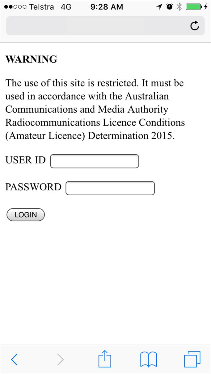
You can securely log into your AIS receiver over your Wi-Fi network to check its operation from another Wi-Fi enabled PC.
- Use your AIS Receiver's IP address discovered earlier (or check your Wi-Fi router's DHCP leases to find it).
- Open a terminal window
- Type: ssh pi@<Your AIS Receiver's IP Address>
- Type: <Your password>
- Display the AIS data being received in real-time as raw NMEA sentences
- Type: journalctl -u aisdispatcher.service -f
pi@AIS:~ $ journalctl -u aisdispatcher.service -f
-- Logs begin at Fri 2020-05-15 19:39:48 AEST. --
May 16 01:26:05 AIS aisdispatcher[438]: !AIVDM,1,1,,B,18JslT0014bGF;5bEibtLqqh0D1A,0*3D
May 16 01:27:12 AIS aisdispatcher[438]: !AIVDM,1,1,,B,4@4k1EQvAGgK;:Etkmb:JM7P00S:,0*10
May 16 01:27:45 AIS aisdispatcher[438]: !AIVDM,1,1,,B,18JslT0014bGEFkbEnwtCIm:00ST,0*75
May 16 01:28:03 AIS aisdispatcher[438]: !AIVDM,1,1,,B,17OetM5P18:GEFwbEp4<=?v80D0U,0*57
May 16 01:28:32 AIS aisdispatcher[438]: !AIVDM,1,1,,B,4@4k1EQvAGgLO:Etkmb:JM7P0L1:,0*7D
May 16 01:28:34 AIS aisdispatcher[438]: !AIVDM,1,1,,B,3815F:Uwh0bGHugbG4U:FWW40r7b,0*48
May 16 01:29:12 AIS aisdispatcher[438]: !AIVDM,1,1,,B,4@4k1EQvAGgM;:Etkmb:JM7P0H7=,0*0D
May 16 01:29:24 AIS aisdispatcher[438]: !AIVDM,1,1,,B,17OetM5P0w:GDcWbEt>LEwvj08><,0*1A
May 16 01:29:44 AIS aisdispatcher[438]: !AIVDM,1,1,,B,17P4895P15:GD;obEwB<8gwJ0@JB,0*7E
May 16 01:30:03 AIS aisdispatcher[438]: !AIVDM,1,1,,B,17OetM5P11:GDG7bEv6<E?v80<0U,0*1A
However, to verify that your data is being uploaded to an AIS server you have to log into it and check your upload statistics - if provided.
Install your AIS Receiver
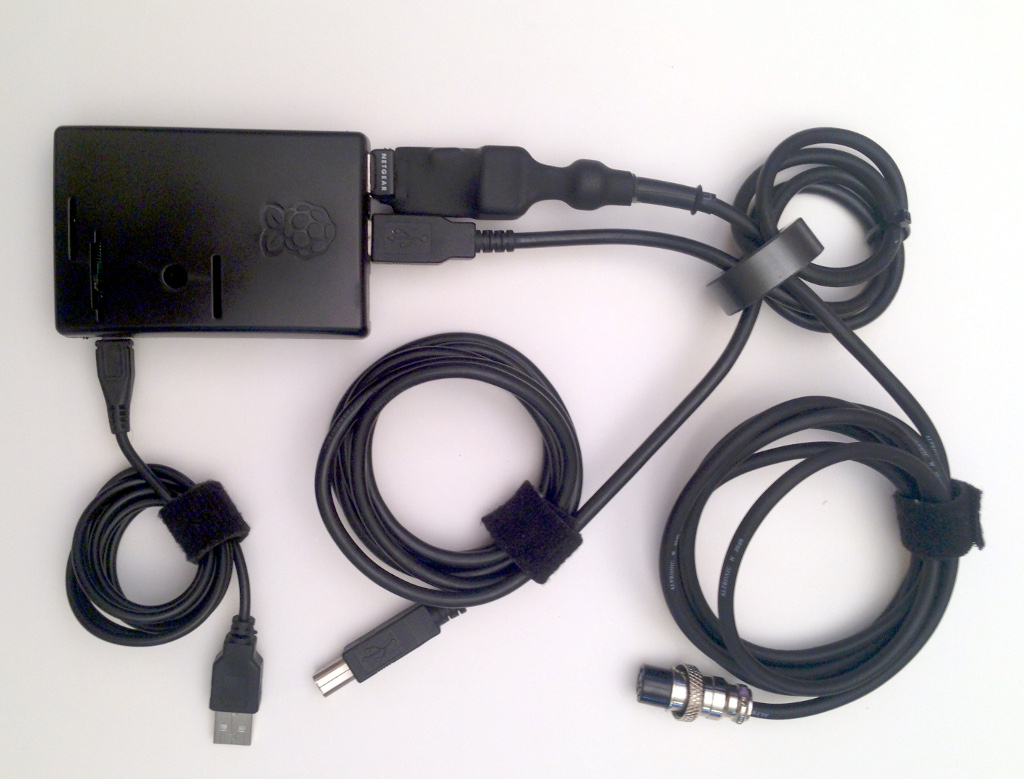
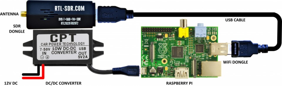
Reconfigure the AIS receiver for stand-alone operation, install it in the enclosure and mount it as follows:
- Disconnect the USB keyboard, HDMI monitor and USB hub, if used
- Assembe the RPi, USB RTL-SDR dongle and 12V to 5V 2A micro USB DC/DC converter in the enclosure
- Connect the 162MHz antenna via the 50 Ohm coaxial cable and an SMA connector to the USB RTL-SDR
- Optionally connect an inline 162MHz AIS Filtered Preamp to amplify the AIS signals and filter out local radio frequency interfrence.
- Connect the 12V DC Adapter via 12V DC Cable to the 12V to 5V 2A micro USB DC/DC converter.
- Mount the enclosure as close to the 162MHz Antenna as possible to reduce coaxial line losses if required. However, inside installations with short lengths of coaxial cable may also be acceptable.
Operate your AIS Receiver
Operating an AIS Receiver station is easy. Just switch it on, let it connect to the Internet and it will receive and upload AIS traffic to the AIS Servers, 24/7.
- Make a backup copy of the RPi SD Card using Win32diskimager.
- Check the operation of the AIS Receiver on a regular basis by monitoring it (as above).
- Check your AIS Servers. Some provide useful AIS Receiver station statistics and on-line maps.
Check the Performance of your AIS Receiver
The AIS receiver will work well on any version of Raspberry Pi with WiFi access - either using the built-in WiFi transceiver or an add-on USB WiFi dongle. Expect the rtl_ais application to run at the following CPU throughput levels:
- 90% CPU on a RPi1
- 66% CPU on an RPi0
- 23% CPU on and RPi2
More information
For more information and credit for the open-source code used in this project please see:
- A simple AIS tuner and generic dual-frequency FM demodulator by D. Giardini: rtl-ais
- An AIS data forwarding utility by AISHub: aisdispatcher